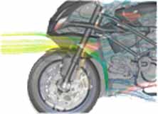
Mechwell Ind. provides design analysis services for specialized modeling and simulations for selected areas of automotive engineering. We offer CAE Technique for solving the most challenging automotive problems. Mech-well provides a CFD solution with a high resolution mesh on a realistic geometry, the physical models to predict accurate Airflow & thermal management, velocity and temperature, humidity for vehicle comfort.

The source of lighting in vehicle headlamp systems has undergone enormous changes over the past few decades. Materials such as glass and metals have given way to high performance materials like durable plastics. Design changes and improvements are bound to happen as requirements and necessities grow each year. Today, automotive industry is highly competitive and focuses more on cost reduction without sacrificing the customer driven requirements and styling characteristics. The main parts of headlamp are the Reflector, Lens and light source. Modern day headlamps are designed with an aim to improve the lighting and thermal distribution within the system. Some factors like longer life span and aerodynamic characteristics can be obtained by utilizing materials like thermoplast reflectors along with plastic lens. Such materials are highly sensitive to high temperatures, so proper and efficient heat transfer analysis has to be done to determine the areas susceptible to thermal degradation. The formation of condensation on the lens surface also causes visibility problems to the driver which would directly lead to the safety of the passengers in the vehicle.Nowadays, simulations through CFD technique is incorporated much earlier in the development stage of an automotive headlamp. Thereby, the automotive industries are able to develop innovative designs with an enhanced performance standard within a reasonable time. The process of physical testing and its validation is available late in the development stage and are also very costly to be performed. Therefore, it is of great significance to simulate the risks during the design phase of the headlamp and henceforth, reduce the cost involved by carrying out proper thermal management studies through numerical analysis and simulations. Transient or steady state analysis is usually done in CFD to study the flow behaviour and thermal characteristics of the system with time. The headlamp assembly CAD geometry is created and discretized in to number of finite elements through the process of meshing. The computational domain is then defined and the respective boundary conditions such as Heat flux from the light source, Convection for the outer reflector and lens is applied. The post processing of results determines the flow distribution of fluid within the system, velocity, pattern of dew formation and temperature spread to determine regions susceptible to thermal degradation. Optimization of the conceptual design is then done to improve the efficiency of the system within the constraints of space and cost by redesigning the headlamp and providing vents at appropriate locations to further enhance the performance and life span of the automobile headlamp. The innovative CAE techniques like CFD can thus be used to predict the thermal behaviour and Fluid flow pattern with in complicated headlamp structures before the actual prototype is being manufactured. Thereby, the CFD technique provides a cost effective and thermally optimized headlamp model to the market.
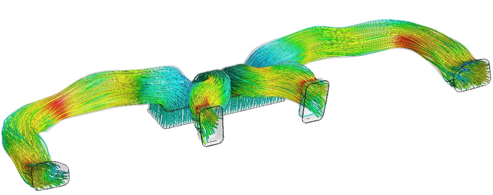
An intake manifold in automobile is the component of engine that supplies the fuel/air mixture to the cylinders. In carbureted engines, the intake manifold connects the carburetor to the intake ports. In fuel-injected engines, the intake manifold connects the throttle body to the intake ports. Intake manifolds work by evenly distributing either air or an air/fuel mixture from the carburetor or throttle body to the cylinders. This is accomplished through careful engineering of both the design and orientation of the manifold. If an intake manifold has too many abrupt changes in orientation or contour, the flow of air can be impeded, which would result in poor operation.An uneven air distribution leads to non-uniform cylinder volumetric efficiency, power loss and increased fuel consumption. During the operation of an IC Engine, pressure waves occur inside the intake manifold. Depending on amplitude and phase of these pressure waves, filling of cylinders can be affected positively and negatively. The amplitude and phase of these pressure waves depend on intake manifold geometry, engine speed and valve timing.
Heating, Ventilation and Air-conditioning (HVAC) systems are of prime importance in vehicles as it enhances the comfort and safety of passengers. Thermal comfort and well-being is achieved by efficient design of the overall thermal management system. The HVAC systems have undergone immense revamp over the years. Nowadays, HVAC systems feature automatic climate control, integrated cooling, heating, demisting and defrosting along with air filtering and humidity control. The competition for space in new vehicles is intense, so the HVAC ducts are often squeezed between different components. Thus, the duct shape can be complex and the design optimization is not an easy task to be performed. In-order to speed up the development phase of the HVAC systems and also to obtain the best possible solutions in-terms of fluid dynamic performance, CFD can be effectively utilized. The airflow directivity within a vehicle cabin is mainly influenced by the air duct orientation, number of air vents, shape and positions. The dynamic air vents are now preferred over steady air vents in high end automobiles. The optimization of geometric design and movement of vanes at certain angle with respect to time in a periodic manner is analysed through the CFD simulations to predict the airflow distribution and relative humidity within the passenger cabin. CFD provides visual streamlines to depict areas prone to flow recirculation and high velocity within ducts and passenger cabin space. It also illustrates generation of vortices caused by groves causing change in flow direction. Defrosting of windshield is not only used to evaluate the HVAC performance but also a mandatory test index for vehicle national standards. CFD simulations are done to predict whether the Defrosting and Demisting system adhere to vehicle safety standards such as SAE J902 or FMVSS 103. SAE J902 specify that 100% "C" zone and 80% "A" zone of the windshield should be cleared within 30 minutes, whereas FMVSS 103 requires 80% "C" zone of the windshield to be cleared in 20 minutes. CFD aids to design and analyse the system level components for product development, meeting the required vehicle standards within short span of time. CFD methodology realizes the design optimization and improved flow characteristics within a reasonable time span and proves to be cost effective.
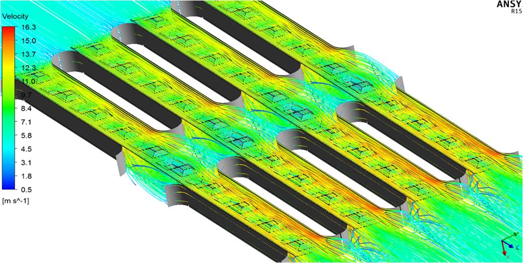
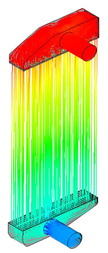
The thermal performence of the radiator in a automotive plays a vital role .The CFD models are widely used to optimize air flow distribution inside the radiator enclosure to enhance the cooling performance of radiator.Mechwell can analize the recirculation zones which leading to hot air pockets which causes degradation of radiator efficiency through CFD .Mechwell Cfd analyis can help to predict velocity & temperature distirbution over a radiator & to predict the ABT(Air to boil temperature)
With the growing awareness on the adverse effects of Global warming, extensive research programs are conducted to achieve higher level of emission reduction from different engine variants to meet the stringent norms formulated and enforced by the government legislations. Greenhouse emissions are considered to be one of the principal sources of environmental pollution. Carbon-monoxide, hydrocarbon, particulate matter (soot) and nitric oxide are primarily identified as major constituents of the emission emerging from diesel engines. Out of these pollutants, NOx and soot emission are considered as most hazardous to the mankind. Different strategies such as the use of optimum blend of fuel, variation in the swirl ratio, variation in the quantity of exhaust gas recirculation (EGR) are tested to determine the reduction in NOx and soot emission rate. Computational Fluid Dynamics (CFD) utilizes its broad range of modelling capability and physics definition to simulate real time phenomenon to perceive the diverse possibilities to achieve the optimum engine design to deliver the expected outcome. CFD incorporates various turbulence models, combustion models and evaporation models to simulate the process of engine emission to study the distinct factors affecting the emission rates. Geometric parameters and intensity of swirl ratios are varied to study the corresponding effects on the rate of emission. The performance and emission characteristics of homogenous charged compression ignition engines depend on achieving a good in-cylinder homogenous mixture. In the CFD analysis, it is evaluated indirectly through contour plots of equivalence ratio, variation of in-cylinder pressure with crank angles, heat release curves or by the comparison of emissions. The mixture homogeneity can effectively quantify the change in fuel distribution pattern in all the conditions of the engine. CFD simulations aid to clearly understand how the injected fuel is distributed in a various ER range inside the combustion chamber. Furthermore, assessment of the influence of piston bowl design and injector offset is analysed to review the performance of the engine under working load. CFD predicts the pressure rise for change in crank angles and determines the peak pressure generated within the engine domain. Analysis are also carried out for light load and heavy load working conditions with variations in the early inlet valve opening and early inlet valve closure. Their effects on fuel economy, emissions and exhaust gas temperature are examined. The cylinder disablement has be an effective strategy to reduce the HC and CO emission under light loading operating conditions. All these different scenarios can be analysed with ease by utilizing CFD methodology. CFD is proposed to be integrated during the conceptual design development phase of the engine to develop vehicles meeting the American Tier 4 and EURO IV emissions standards of the respective nations. Parametric study of diverse components through CFD analysis can be done to develop an engine with enhanced performance standards. Thus, the CFD methodology presents a simulation strategy to produce a cost effective and thermally optimised engine prototype to the global market.


